198
X3
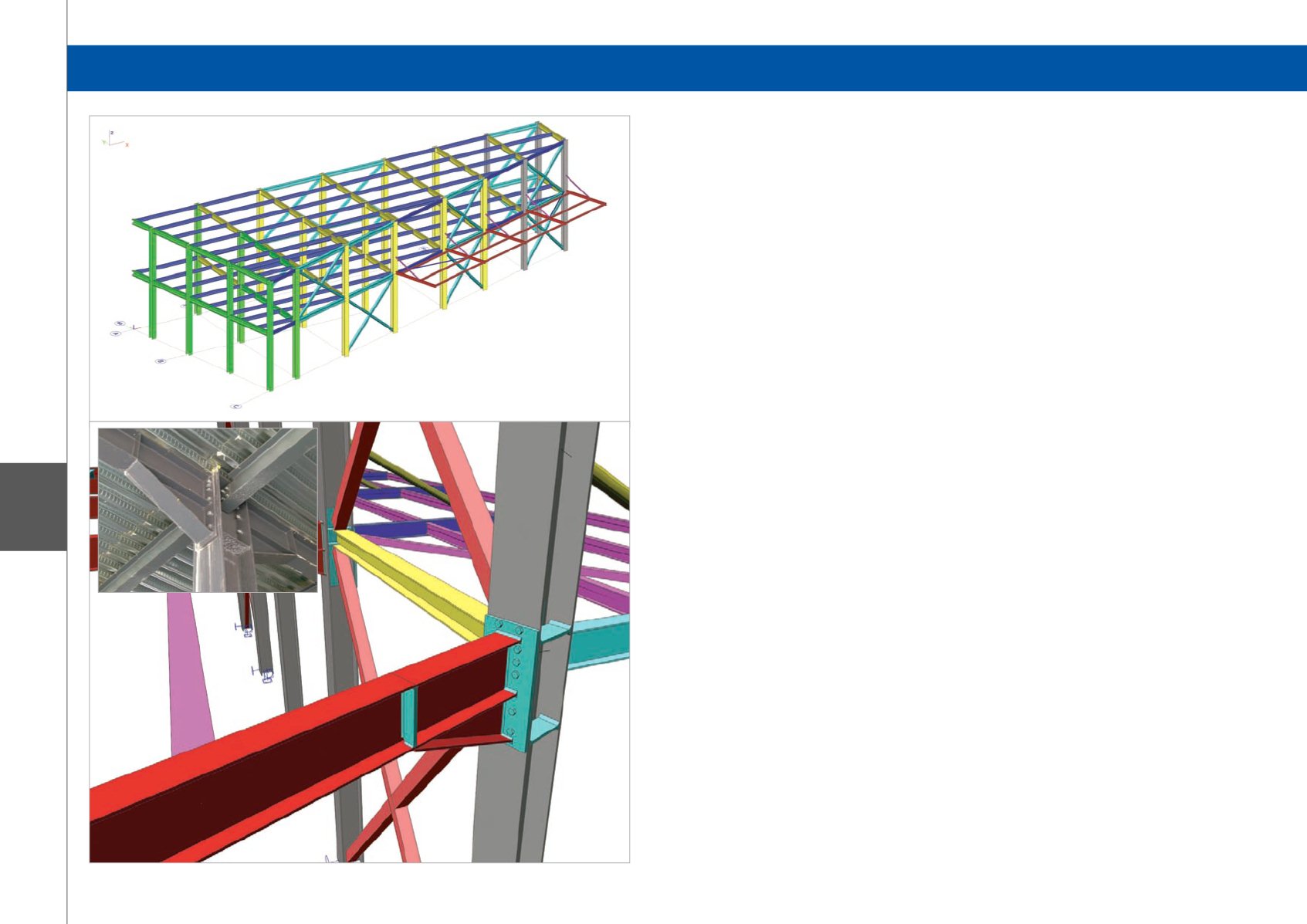
Category 3: Industrial Buildings and Plants
Introduction to the project
This project includes the extension of an existing
industrial baking plant founded in 2004 in Chania, the
second largest city of Crete.
The existing part of the plant is a two-floor building with
a basement, made from reinforced concrete.
The extension includes a two-floor composite structure
of steel and concrete. The total area of the plant is
about 1,600 sqm. This year we are designing a new
extension, of about 200 sqm.
Description of the project
The whole structure comprises of three separate
buildings. The existing building is made from reinforced
concrete and the extension is made from steel and
concrete. Due to the geometry of the extension, we
decided to design it as two separate buildings matched
together with a seismic joint.
Approach
Extension Part A
The distances between the columns of each frame are
from 3 m to 6 m. The distances between the frames
are from 4 m to 6 m. The dimensions of the building
are 28 m x 13 m and the height about 7.50 m. We used
HEA for the columns, IPE for the main and secondary
beams and an SHS cross-section for the roof bracing.
Extension Part B
The distance between the columns of each frame is
about 6 m. The distances between the frames are about
3 m. The dimensions of the building are 15 m x 6 m
and the height is about 7.50 m. We used HEA for the
columns, IPE for the main and secondary beams and an
SHS cross-section for the roof bracing.
For both parts of the extension, the secondary beams
were designed using the composite beam module in
order to reduce the total weight of steel.
To simulate the diaphragm of the concrete slab,
HEA1000 was used for the roof bracing, without weight
and mass, using property modifiers.
The use of Scia Engineer in this project
We designed the 3D Model, using the Line Grid option.
The next step was to make all the load cases, load
groups and load combinations.
Load groups:
1. G : permanent
2. S : snow
3. W : wind
4. E : seismic
5. Q : variable
Load cases:
1. LC1 : self-weight
2. LC2 : permanent
3. LC3 : variable
4. LC4 : snow
5. LC5 : seismic X
6. LC6 : seismic Y
7. LC7 - LC22 : 3D Wind Load Cases
Load Combinations:
1. EN-ULS
2. EN-SLS
3. EN-seismic X
4. EN-seismic Y
For the wind loads we used the 3D wind option to
calculate with accuracy all the zones according to
EN1991-1-4.
For the permanent loads and snow, we used line forces
on beams.The seismic design followed EN1998.
After the linear and the modal analysis, we conducted
section and unity checks for all the members. We also
proceeded to a serviceability check for the main beams.
Software: Scia Engineer
Extension of Two-Floor Industrial Baking Plant - Crete, Greece


