110
X2
Nomination Category 2: Civil Structures
City Bridge - Nijmegen, The Netherlands
Introduction
The city of Nijmegen is building a new bridge across
the river Waal to improve the accessibility to the city
and traffic flow. The bridge will be built at the historical
location known as “De Oversteek” (“The Crossing”),
where American soldiers crossed the river to secure the
existing Waal bridge during Operation Market Garden.
The existing Waal bridge, dating from 1936, was at the
time of completion the biggest arch bridge in Europe
with a span of 244 m.
The contract to design, build and maintain the new
bridge crossing the River Waal at Nijmegen was
awarded to a consortium after a design competition in
2009.
The bridge has the total length of 1,400 m. The
southern approach bridge on the Nijmegen side lies in
a curvature with the radius of 500 m. The main span,
with the length of 285 m, consists of a single tied arch
structure and crosses the river Waal in a straight line,
while the northern approach bridge is in a horizontal
curvature of 2,000 m.
Design of the approach bridges
The approach bridges consist of a succession of
concrete arches. The spans of these arches are 42.5 m.
The thickness of the arches at the columns is just under
1.5 m and in the centre of the span 0.5 m. The void
above the arches is filled with foam concrete to reduce
the weight on the arches and covered with mixed
aggregates and asphalt layers.
The total continuous length of the approach bridge at
the north side equals 703 m, including the abutment
at the Oosterhoutsedijk. The length at the south side
equals 275 m. The concrete arches of the northern and
southern approach bridges are rigidly connected to the
bridge columns and have no expansion joints.
Modelling with Scia Engineer
The approach bridges were modelled in Scia Engineer
using a 2D beam model for the preliminary and final
design stages.
Geometrical non-linear calculations were carried out
with the 2D beam model. With this model the buckling
shapes of the arches were investigated and the second
order moments were calculated.
To keep the bridge stable during the construction
stages, a prestressed tensioning system of bars and
beams, spanning between two arch crests, was set in
place to take over the thrust force from the arch, which
came into action as the falsework was removed. A
second 2D beam model was set up to determine the
force distribution during the various construction stages.
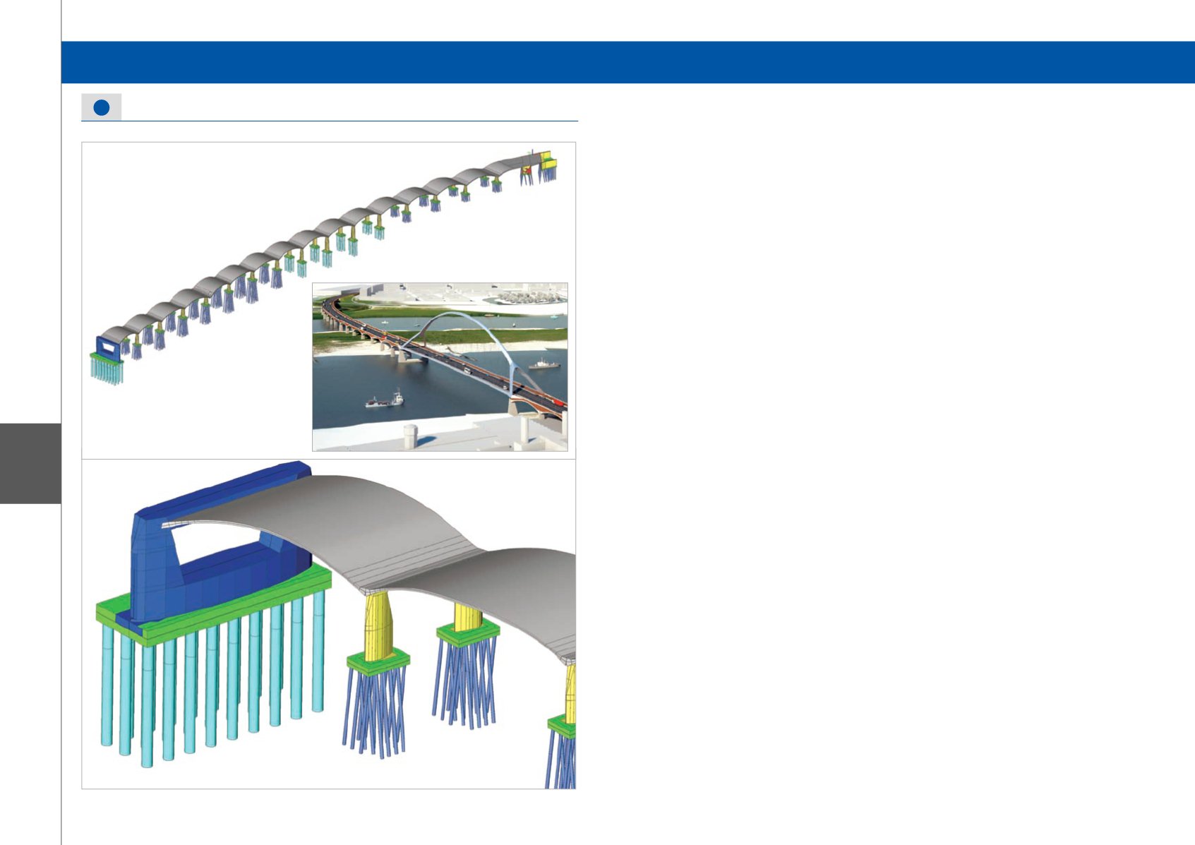
For the detailed design stage, a 3D model has been
created consisting of shells, beams and plates. The
horizontal curvature of the bridge, the changing angle
to every support axis and the varying width of the in
plane curved arches has been taken into account. Also,
the complex shapes of the columns and river pier have
been modelled. The piles with different lengths and
horizontal and vertical spring stiffnesses for every axis
were also modelled in the model.
The loads and load combinations according to the
NEN-EN codes were applied. These loads included
dead loads, creep and shrinkage loads, traffic loads,
temperature loads, wind loads, support settlements,
accidental loads and earthquake loads.
With the 3D model the internal force distribution
was determined in order to design the required
reinforcement. Moreover, the pile design has been
carried out using the results of the 3D model.
Software: Scia Engineer
Nomination Category 2: Civil Structures


