114
X2
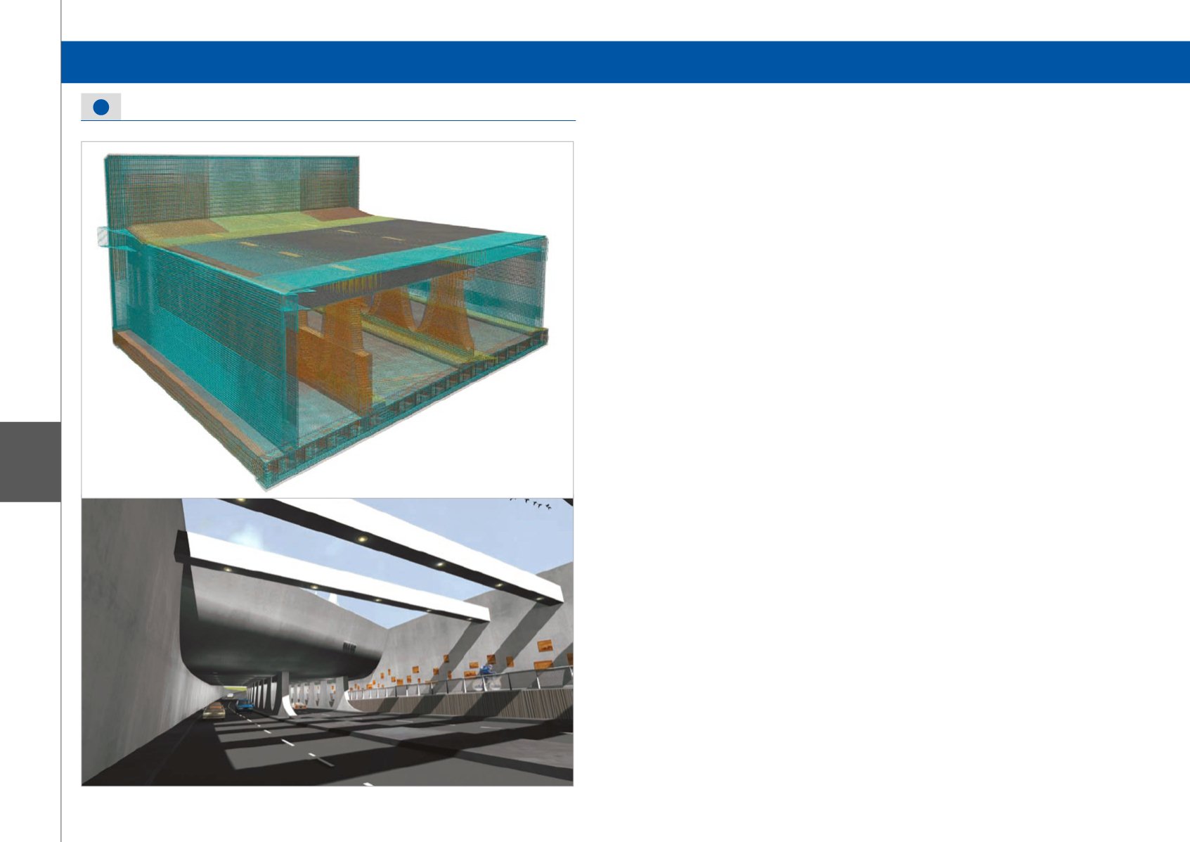
Detail engineering, Aqueduct Westelijke Invalsweg
Based on the architectural requirements, the front wall
of the aqueduct at the East and West entrance should
have a rounded shape with the radius of 5 m. There
were two different structural options available.
The first option was a complex round shape with
in-situ concrete. This option would lead to very large
dimensions and complex formwork.
The second option was a simpler rectangular aqueduct
with prefab concrete shell parts. The extra space on the
surface level can be used for the service path.
The second option was chosen since from the design
point of view it was less complex and easier to
construct.
For the dividing walls beneath the aqueduct, the
architect had the design requirement that 60% of the
area be “gaps”. So the choice was made to make the
dividing walls upside down ellipsoid shapes. This was
meant to evoke the image of Roman-era aqueducts.
Pergola construction
The horizontal struts near the East Entrance should be
made in concrete and create a lamella roof impression
according to the architectural requirements.
With the presence of the permanent struts in the
deepest part of the access ramp, the choice for a
pergola construction was obvious.
The struts are made from pre-cast pre-tensioned girders
with the dimensions of 800 mm width and 1,350 mm
height.
Centre-to-centre: 5,000 mm.
Because of the regularity of the supports, a slim deck
slab with the thickness of 400 mm could be made.
Ingenious poldering
The West Entrance should be made with an open green
character. In the preliminary design an artificial polder
containing a geomembrane was foreseen.
After the soil and geotechnical research had been
carried out, a strong water-resistant loam layer was
identified at the West Entrance. Based on this layer, the
design was optimised.
The project in Allplan Engineering
We started from scratch with three MX-axes.
One for the cycle path and one for each carriageway.
With the design constraints in mind, the model was
generated using the Bridge and Tunnel Modeler.
After its completion, the model was checked thoroughly
by examining the design constraints one by one.
When the main model was finished, the aqueduct
casing, water cellar and the horizontal struts were
modelled separately.
We chose a separate design option because the last 3
parts of the model where not curved design-wise. For
the main tunnel the segmentation was 2.5 m. This was
chosen as it was the segmentation by which the building
tolerance was within prescribed measures.
When the model was ready, dimension drawings
were made. For this the model had to be divided into
separate tunnel sections, each section as a separate
dimension drawing.
After completing the calculation, the rebar modelling
could start.
All rebar was modelled in 3D.
Summary
• Total sections: 19
• Length of concrete sections 2-20: approx. 390 m
• Length of polder section, west side: approx. 195 m
• Closed part: approx. 55 m (sections 6-7)
• Internal height, closed sections: 5.3 m
• Internal width: 22.6 m
• Number of drawings: approx. 120
Aqueduct, Part of the “Westelijke Invalsweg” Project - Leeuwarden, The Netherlands
Software: Allplan Engineering
Nomination Category 2: Civil Structures
Nomination Category 2: Civil Structures


