210
X4
Winner Special Prize for Fabrication and Execution
Software: Scia Engineer
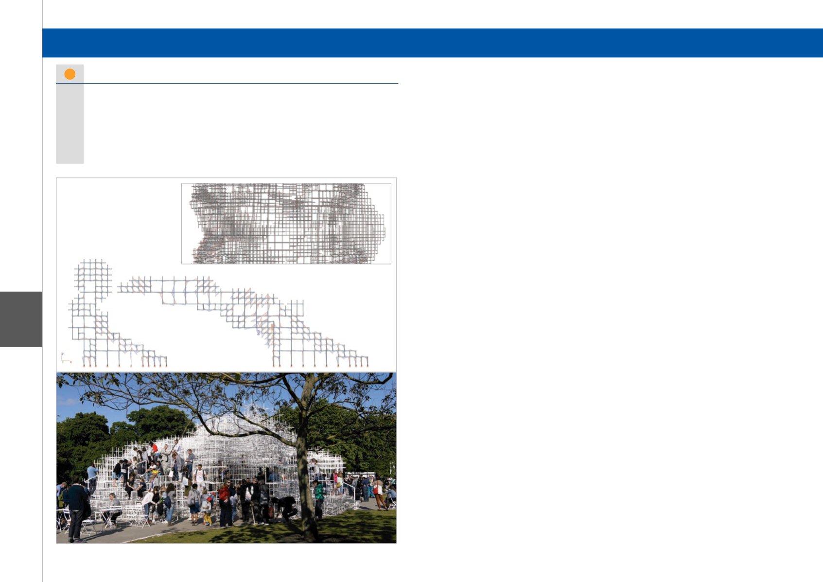
Serpentine Gallery Pavilion 2013 - London, United Kingdom
Each year, the Serpentine Gallery commissions an
international architect to design their summer pavilion.
The 2013 Pavilion was designed by Japanese
architect Sou Fujimoto, with AECOM carrying out
the structural design from concept stage in January
2013 to completion in time for the press launch on 4th
June 2013. The Pavilion exemplifies contemporary
architecture and the engineering challenge is to mask
the complexity of the structure behind simple design
and intelligent detailing.
Concept
The concept is built around a three dimensional 400 mm
grid, with 20 mm square hollow sections forming a
vierendeel space frame which provides areas of shelter,
formed by the addition of circular polycarbonate discs,
as well as areas where guests are invited to climb over
the structure.
Design
The complex nature of the structure meant that a
three dimensional analysis model was essential as
the structure relies on all 27,000 members for global
stability. In the areas where guests are permitted access
onto the structure, locally high loading was imposed
to allow for the weight of the glass infill panels and the
weight of a crowd gathered on the structure. This was
combined with accidental load combinations which
accounted for unwanted access onto the roof, member
removal and settlement of the footings.
Testing
From the outset it was clear that the detailing of the
nodes was vital; they needed to be simple to fabricate,
allow easy construction of larger modules for delivery
to site as well as on site, connections, and they needed
to be able to transfer the full moment capacity of the
section across the joint.
Several concepts were drawn up and design sessions
with the fabricator (Stage One) allowed a detail to be
developed which allowed the structure to be constructed
in the available timescales. Separate details were
needed for the site connections.
It was necessary to ensure that the joint could mobilise
the full moment capacity of the steel section as this
was fundamental to the stability of the structure, which
relied on vierendeel action of the frames and the
corresponding high moments at node points. To ensure
that the capacity of the joints was sufficient, several
test pieces were created and tested to destruction. This
included small scale single nodes as well as large scale
mock ups of portions of the structure.
Parametric design process
The success of the scheme relied upon electronic
collaboration between the design team members.
From the outset of the project the design concept was
conveyed using 3D models, as the complex structure
has very little meaning when expressed as two
dimensional sections. The architectural scheme was
drawn up using Rhino and bespoke scripts were used
to transfer the geometry to Scia Engineer. Fundamental
to the success was the ability to make this a complete
round trip process, allowing rapid design development
with the architect and iteration of the design to a final
solution which embodied the architect’s dream as well
as functioning structurally.
The 3D model was also shared with the fabricator
allowing integration with their computer aided
manufacturing processes, as well as better visualisation
of the structure and optimisation of the size of the
fabrication modules for delivery to site and erection
within the short construction period on site.
Structural design drawings were produced in AutoDesk
Revit. The geometry was transferred to Revit using the
Revit-Scia Engineer link.
Winner Special Prize for Fabrication and Execution
Quote of the Jury:
“The concept of this reusable structure was drawn up using Rhino and
bespoke scripts were used to transfer the geometry to Scia Engineer for structural analysis
and design. The 3D model was also used for computer aided manufacturing (CAM), as well
as for better visualization and optimization of the size of the fabrication modules for onsite
delivery and erection. The geometry was transferred from Scia Engineer to Revit for producing
the structural drawings. Due to the different partners involved and the short project time, the
use of Building Information Modeling (BIM) was essential to make this project a success.”


