220
X4
Category 4: Special Projects
Roof Structure Noorderpark Subway Station - Amsterdam, The Netherlands
Introduction
In the city of Amsterdam a new subway line is being
created that connects the Northern part of Amsterdam
with the Southern part. The line runs underneath the
city centre, the central railway station and the waterway
known as ‘het IJ’.
One of the newly built stations is Noorderpark, located
north of ‘het IJ’, where the subway emerges from
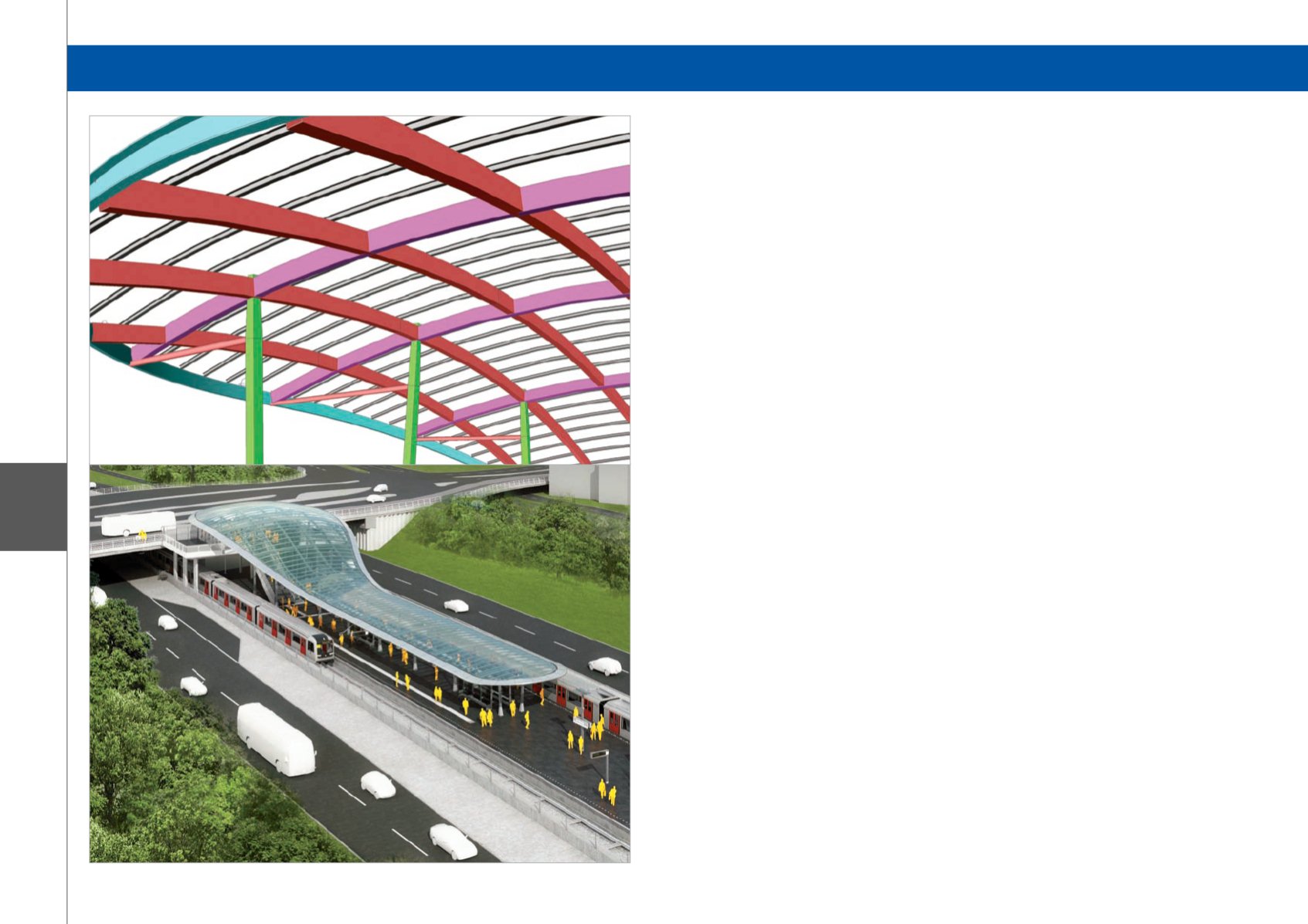
underground. The station will be fitted with a glass roof
structure supported by steel beams and girders.
Architectural Design
The design is provided by Benthem Crouwel Architects
and consists of a transparent smooth roof surface
of cold-bent glass. The bend line of the roof edge is
characteristic. The vertical and horizontal curvatures
follow the spatial structure of the station.
Stuctural Lay-out
The structural lay-out consists of main beams in the
transversal direction, supported by slanted columns.
The slanted columns provide the stability of the roof
structure. The purlins supporting the glass, of which the
spacing is adjusted to the size of the bent glass panels,
are supported by long curved beams in the longitudinal
direction.
Challenges
The complexity of the project mainly lies in the
geometry. The roof is constructed by assembling
different spherical shapes and intersection surfaces
to create a completely smoothly curved surface in all
directions. All this is done by an analytical approach
to parameterise the design in such a way that the
constraints given by the maximum size and repetition of
the glass panels are always satisfied.
Another complicating factor was the substructure of
the platforms and entrance plateau, already built and
designed for the totally different former design of the
roof structure.
Finally, considering the bended geometry in all
directions, it was a tedious job to determine and input
all the different windloads on the structure. Wind suction
as well as wind pressure had to be taken into account
for different wind directions and different parts of the
structure.
Modelling approach
The shape of the roof was modelled with the modelling
tools available in Scia Engineer to create spherical
bodies. The final shape was then intersected by
surfaces. In the intersections the steel beams and
girders were modelled.
Finally, since many different combinations of forces at
the supports were generated, a governing part of the
already built substructure was modelled to check if any
reinforcements were needed.
Optimisation
Since the structural design was parameterised from the
offset and modelled in Scia Engineer, different variants
for the geometrical shape as well as the used steel
profiles could be analysed and compared quickly. Thus
an optimal design in terms of shape, steel usage and
ease of erection is reached, all tailor-made to the cost-
effective usage of cold-bent glass.
Software: Scia Engineer


