262
X4
Category 4: Special Projects
Burial Sledge System II - Rotterdam, The Netherlands
Project description
When offshore windfarms are built, offshore cables
have to be installed to transfer the energy to the shore.
These cable routes frequently cross shipping lanes
and for reasons of protection these submarine cables
often have to be buried. Due to seabed migration, cable
owners installing new cables more often demand an
increase of the burial depth in order to reduce the risk
of exposure to, and eventual damage and failure of, the
submarine cable. Deeper burial depths are potentially
problematic since there are few tools available to
realise such burial depths. The Burial Sledge System II
(BSS-II) is a system that can realise burial depths of up
to 6 m under the seabed.
The submarine cable that has to be installed under the
seabed is deployed from a cable-laying barge to the
lance mounted on the sledge. Fluidising in front of the
lance makes the soil weak enabling the lance to install
the cable at the agreed depth. Because the jetting lance
is mounted on a sledge which rests on the seabed, the
cable burial operation is a lot less dependent on the
actual sea state which makes the operations safer for
the cable as well as the personnel.
Geometry
• Height: 18 m
• Length: 20 m
• Beam: 12 m
Specifications
• Max. pulling force: 100 t
• Burial depth: Max. 6 m under the seabed
• Weight of sledge: 50 t
• Weight of lance: 20 t
• Water depth: 0-30 m
Loads on the sledge
• Wave forces
• Current forces
• Soil reaction forces during burying
• Pulling forces on the sledge, while moving
Software used for this project
• Scia Engineer: structural analysis and design
according to the Eurocodes.
• Autodesk inventor: 3D Mechanical Design Software.
• Orcaflex: dynamic analysis of offshore marine
systems.
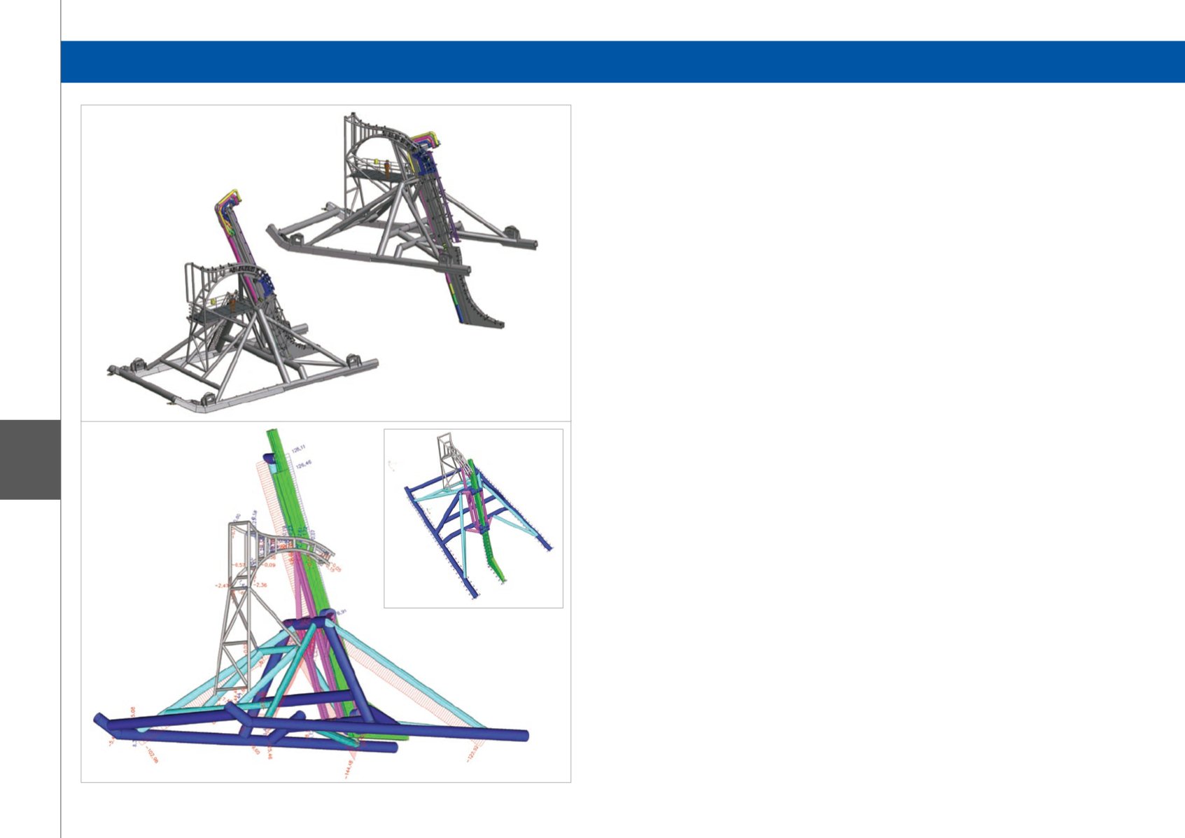
The use of Scia Engineer
The whole structure of the sledge, combined with the
lance, was modelled with Scia Engineer.
The calculation included several aspects:
• The modelling of the complex BSS II structure.
• The modelling of the sledge soil foundation at the
seabed-level with non-linear springs to schematise
the soil.
• The modelling of the environmental forces (like
waves and current forces, depending on the water
depth) into static load cases (the dynamic calculation
was performed with ‘orcaflex’).
• A non-linear calculation of different load cases and
situations (different water depths, different lance
depths under the seabed).
• A Eurocode check of the steel structure.
Challenges with Scia Engineer
• The complex structure.
• The modelling of the non-linear soil at the seabed
level.
• The modelling of the non-linear soil under the
seabed.
• The modelling of the environmental forces.
Software: Scia Engineer


