contraction during start-up and shutdown is also taken by
the structure. The steel structure is designed as self-
supporting static system,
which creates stable unit due to its
dam walls and rigid beam grid on every platform level, able
to transfer horizontal and vertical forces into foundations.
The structure creates one independent expansion block.
The steel structure is mostly open,
with the exception of
wall cladding between elevations +9,450 and +18,650,
which is stiffened by auxiliary columns and cross-bracings.
Protection wall is also made on elevation ±0,000 on three
sides of the structure up to the height of +4,000 m.
Main footprint dimensions of the structure are given by
axes A, B, 1, and 2: 7,30 x 6,60 m. Auxiliary columns for
supporting of extra platforms between elevations +9,450
and +18,650 are in the intersection of axes A, B, 1´, 2´ in
the distance 3,450 m, resp. 2,450 from main axis 1, 2
Access to relevant platforms is enabled via side steel
stairway. Stair beams are made of rolled steel beams, steps
are made of galvanised gratings.
Description of the Parts of STEEL STRUCTURE
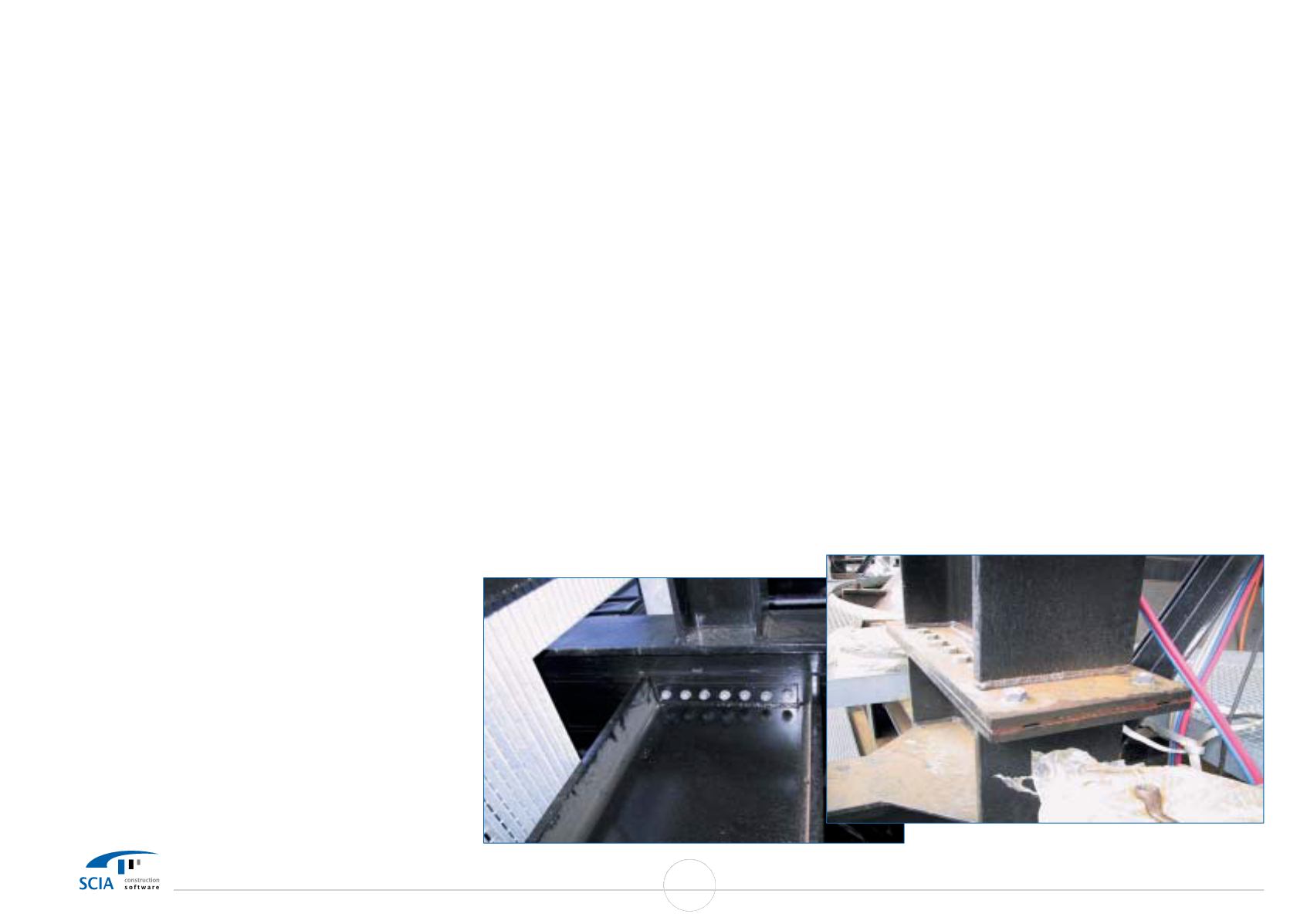
Columns are
made of broad-flanged rolled beams HEB.
There are erection joints on two elevations of the structure.
Most loaded points are stiffened
with transverse beams.
Four anchoring bolts
with T-heads anchor the structure
into the foundations. Transversal beams are made of open-
section rolled steel beams. The beams are partly supported
or hanged into diagonal cross-bracings in the fields
between columns. Parts are connected with bolts in the
erection phase. The beams are secured against yawing
with transversal beams in the pitch of 1 m max., the latter
serving also as supports for galvanised grid covering of
platforms. Diagonal cross bracings are
made of pairs of
open-section rolled steel beams. Connection to columns
and beams is made through steel sheet flanges and bolts.
Platform beams are made of system of rolled steel beams.
Platforms are covered
with hot dip galvanised gratings
fixed to platform beams with fixing elements. The platform
edges not protected with cladding walls are equipped with
kick plates and railings. Two tracks for SCC access doors are
fixed to platforms on elevations +15,150 a +28,920.
Auxiliary stairs are made in the area of several platforms,
thus connecting relevant platforms. The roof of cladded
part of the structure is made of tear-drop steel sheets with
thickness of 6 mm at the elevation of +18,650. The steel
stairway is opened to the wind.
Minimumwidth of the stairs
is 800
mm and
maximum slope is 45°. Stairs between
relevant platforms are
made of sloped steel
U-shaped
beams. Stair steps are made of galvanised gratings fixed
with bolts. Resting platforms are equipped with kick plates
and railings on the edges.
Description of the method of Static calculation
Static calculation is prepared
with software IDA-PRIMA -
integrated graphic computing system for static calculation
by finite element analysis (FEA). It enables complex linear,
non-linear, dynamic and stability design of any structure
created by bars. Sizing of elements is in accordance with
standards listed above.
Deformations of the nodes
The text enclosure C pages 1-50 (plastic index sheet No. 7)
shows deformations of selected nodes in relevant load case
combinations, the same in graphic enclosure F (plastic
index sheet
No.). The nodes
were selected in all four
corners on each platform elevation.
Horizontal deformation in x, y direction should not exceed
1/500 of node elevation above support (of the structure as
whole) acc. to recommended limit deformations in ENV
1993-1-1:1992,
Eurocode
3. The software evaluates
extreme deformations in every direction separately (x, y, z)
as well as maximum node rotation around axes x, y, z.
At
the evaluation on page 52 it is shown, that the node with
most
extreme
deformation is
node
No.
633
with
deformation 55,8 mm in axis y. Since the nozzle is at the
elevation of 28,920 m above the support, its deformation
should be no more than 28920/500 = 57,9 mm,
which is
acceptable. Since the columns in the x-axis posses larger
modules of inertia, the deformations are much smaller in
this direction.
Deformations of bars
The text enclosure C page 53 (plastic index sheet No. 7)
shows extreme deformations selected from all bars in steel
structure, the same in graphic enclosure F (plastic index
sheet
No.). Since printed output for each bar
will be
extremely large, deformations of selected bars are also in
graphic enclosure F (plastic index sheet No. 10) -
mostly
beams bearing the SCC. In this case,
maximum deflection
should be no more than 1/250 of beam length (about 26,5
mm) acc. to recommended limit deformations in ENV 1993-
1-1:1992, Eurocode 3,
which was met in each case.
81
SCIA User Contest Catalog


