Amsterdam ArenA, Dynamic recalculation of roof structure
ARCADIS Bouw en Vastgoed
Gevers Deynootweg 93
Postbus 84319
2508 AH Den Haag
The Netherlands
Tel: +31 70 358 3583
Fax: +31 70 354 6163
Contact: ir.
M.J.
W. van Osch
Email:
Contact: ir.
A.M. de Roo
Website:
In buildings, consideration needs to be
given to combining functionality,
mainte-
nance aspects, economic en ecologic fac-
tors,
wherever people gather. That's our
mission at
ARCADIS. Public, institutional
manufacturing and commercial clients reap
the benefit of our extensive services: indus-
trial
plant
know-how,
redevelopment
expertise, turn-key location solutions,
multi-
functional site development, such as ultra
modern stadiums and stations, and total
facility
management. Always safeguarding
the human factor while ensuring investors'
stakes.
We call it building a better tomor-
row.
What are the main activities of our
company?
The four core activities of ARCADIS are:
Infrastructure, Buildings, Environment and
Telecommunications
What is the annual turnover?
The total turnover worldwide is an estimat-
ed 850 million euro.
ARCADIS is involved in
more than 10.000 projects each year in over
100 countries.
How many staff does our company
have?
Approximately 8500 people
worldwide,
3000 people in the Netherlands.
Introduction and history
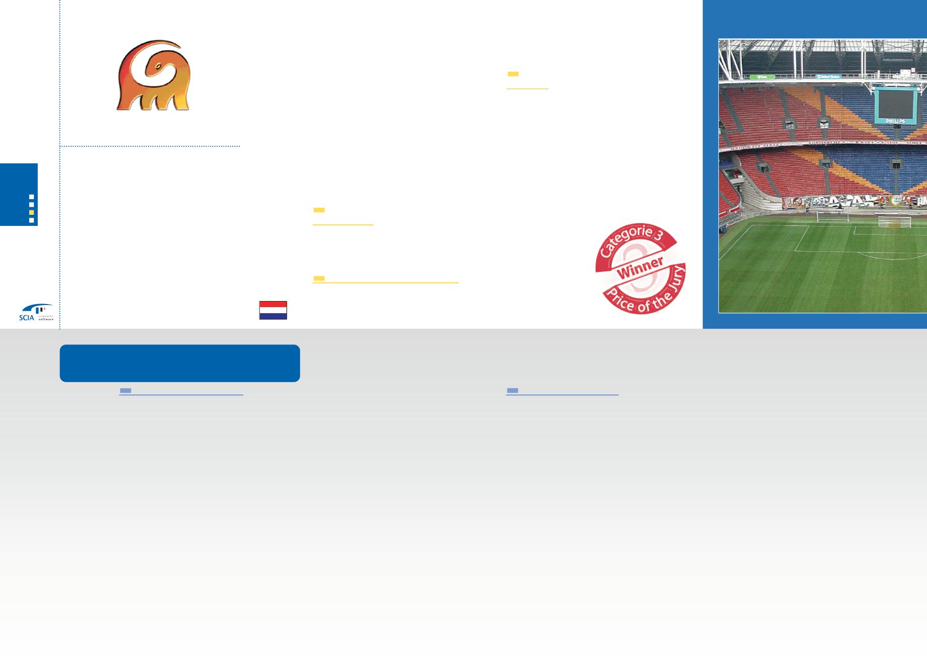
In 1993-1995, the Amsterdam ArenA
was
designed and constructed. This
multipur-
pose stadium is located on the southeast of
Amsterdam, close to several highways, rail-
ways and over a minor highway. The first
two floors are parking garage.
Above these,
the playing field and tribunes rise up to
approximately 44
metres above the sur-
rounding fields. A transparent steel struc-
ture forms an oval roof over the tribunes.
The centre void in this roof can be com-
pletely closed by two
movable segments.
This
makes this structure very suitable for
sports and other activities, such as concerts.
Especially during the activities other than
sports, the roof structure is used frequently
to hang tons of audio-visual equipment and
components of the set.
The main structure of the roof is formed by
a giant
H-frame (177x126
metres). This
frame spans the field and the tribunes and
consists of triangular trusses of several
metres in height.
On this H-frame, the oval
shaped roof-plane is suspended. Also, the
movable segments ride on top of this frame.
The design of the steel roof structure was
carried out using Strucad. By then, it
was
not possible to
model the complete struc-
ture. Loads and stability-effects of the oval
roof-plane and the movable segments had
to be derived separately.
All loads, including
wind, have been applied statically.
Using
this
model, the structure
was optimized
quite extremely.
In the following years, the grandiosity of
happenings grew enormously, increasing
the temporary loads and bringing the struc-
ture closer to its limits.
Right now, the city of Amsterdam is devel-
oping the area around the stadium. In these
plans, two towers of about twice the height
of the stadium are posted directly next to
the stadium. These towers have a great
influence on the wind loads on the roof of
the stadium.
Wind tunnel tests showed a
(local) static increase up to 30%. Feasibility
of these towers depended on the strength
of the roof structure.
Sophisticated analysis
The total of increasing loads asked for a
more sophisticated analysis of the structure.
Using the existing design, the whole struc-
ture was remodelled in ESA-Prima Win 3.50.
Profiles,
hinges, supports, offsets of connec-
tions, all
were copied from the original
design. EPW
was chosen because of the
clarity and easiness of the input, but also
because of the great possibilities to (visually)
check and
modify the complex structure.
This was very workable during the process
of modelling and validating the H-frame.
Not only was the H-frame modeled, also the
frame of the oval roof-plane over the trib-
unes and the frame of the
movable seg-
ments on top of the H-frame. This made it
possible to apply the
wind loads directly
were they are supposed to act.
In a large area like the roof of a stadium,
wind loads will never peak at the same time
on the whole surface. Static loads are there-
fore considered to be too conservative.
Using the results of the wind tunnel tests,
wind has been incorporated in ESA-Prima
Win as dynamic nodal loads. In close consul-
tation
with the people of ESA, following
steps were taken:
1.
Wind tunnel tests produce a continuous
pressure parameter for approximately 50
locations on the roof;
2.
From these results, for some significant
situation (wind directions, 1 or 2 towers)
the
minute has been derived in
which
the wind load is maximum;
3.
For each of the 50 locations, the contin-
uous pressure has been described by a
Fourier-analysis of 10 sinuses;
4.
For each cross of
main girders of the
roof, the area has been calculated. The
size of this area, combined with the pres-
sure-functions
which act in this area,
result in the (variable) force on that
node;
5.
Since the roof is a 3-dimensional plane,
for each node the normal vector is differ-
ent. This normal vector of the roof is
94
Company
Project
Amsterdam ArenA, Dynamic
recalculation of roof structure
SCIA User Contest 2005 / Commercial and industrial building
3
Categorie


