Our worldwide references emphasise the global nature of
our company.
Experience gained from
more than 100 completed
installations provides the necessary resources for offering
the total solution for the optimal treatment of a vast array
of different waste streams.
Bart Gevaerts works at SOLIDS + AIR division as Design
Engineer for the Mechanical Design Department and as
Project Engineer
Your Project:
Description
The Seghers Sludge Pelletiser is a device developed to dry and
palletise (make pellets) sludge.
This is principally done by transporting the sludge over trays,
heated internally by thermal oil to typically 250 °C.
The device therefore consists of a vertical tower structure in
which the trays are stacked.
Centrically a shaft
which drives a scraping
mechanism to
transport the sludge is placed.
Typical data: nr of trays in 1 Pelletiser: up to 23
Diameter of tray:
5200/6200 mm
Weight of 1 tray:
7500 kg
Weight of driving shaft + scrapers:
30 tons
Weight of shell structure:
tons
Height of pelletiser:
up to 20 m
This design was firstly used at the BESOS-plant (Spain), for 4
Pelletisers of 17 trays each This means a total of 17*4 = 68
trays!
The shell structure of the Pelletiser
1. Structural design
Basic structure,
which
was designed using ESA-Prima WIN
consists of a steel structure, covered by flat plating: this part
carries the trays of the Pelletiser. Bottom part is a cylindrical
and conical structure, supported on steel columns. On the
central conical structure, the driving shaft and main drive is
supported. A complete analysis model could be made because
of the possibility in PRIMA WIN to make a combination of 2D,
3D and 1D elements.
Because a complete model
was built during the design, this
was a very interesting basis for making up scaling models (by
very easily copying existing modelled structure and loadings)
in later projects: eg.
Model of 5200 pelletiser for BESOS-plant
was upgraded to 6200 pelletiser for TAY plant (Scotland).
2. Loading data
Design of the device consists of calculation and evaluation of
a number of load cases and their complex combinational
effects:
Own weight of shell structure
Loading by trays
Sludge loading on trays
Internal pressure of the shell during operation
Loading of bottom by shaft and main drive
Wind loading during erection
Temperature loading: shell structure obtains a higher
temperature as column supports during operation,
which
leads to thermal stresses.
·
Top loading: on top of pelletiser a hopper, sludge coater
and thermal expansion tank are mounted
Using this
model evaluation
was
made of deformations of
plated structure, stresses in plates, stress concentrations at
support-points
Thermal trays
1. Deformation characteristics of thermal tray
Design of the thermal trays is determined to a high degree by
the amount of deformation (by own
weight, thermal oil,
loading of the tray with sludge).
This is investigated by means of a complete F.E.M.
model to
calculate, evaluate and minimise these deformations.
In 2000, a new design of thermal tray was made, and a test
stand was built in workshop to measure the deformations of
the tray; a very accurate agreement between realisation and
calculations was found. Calculation of behaviour of the tray at
operation temperatures was done by reducing the E-modulus
of the material in the calculation and recalculation.
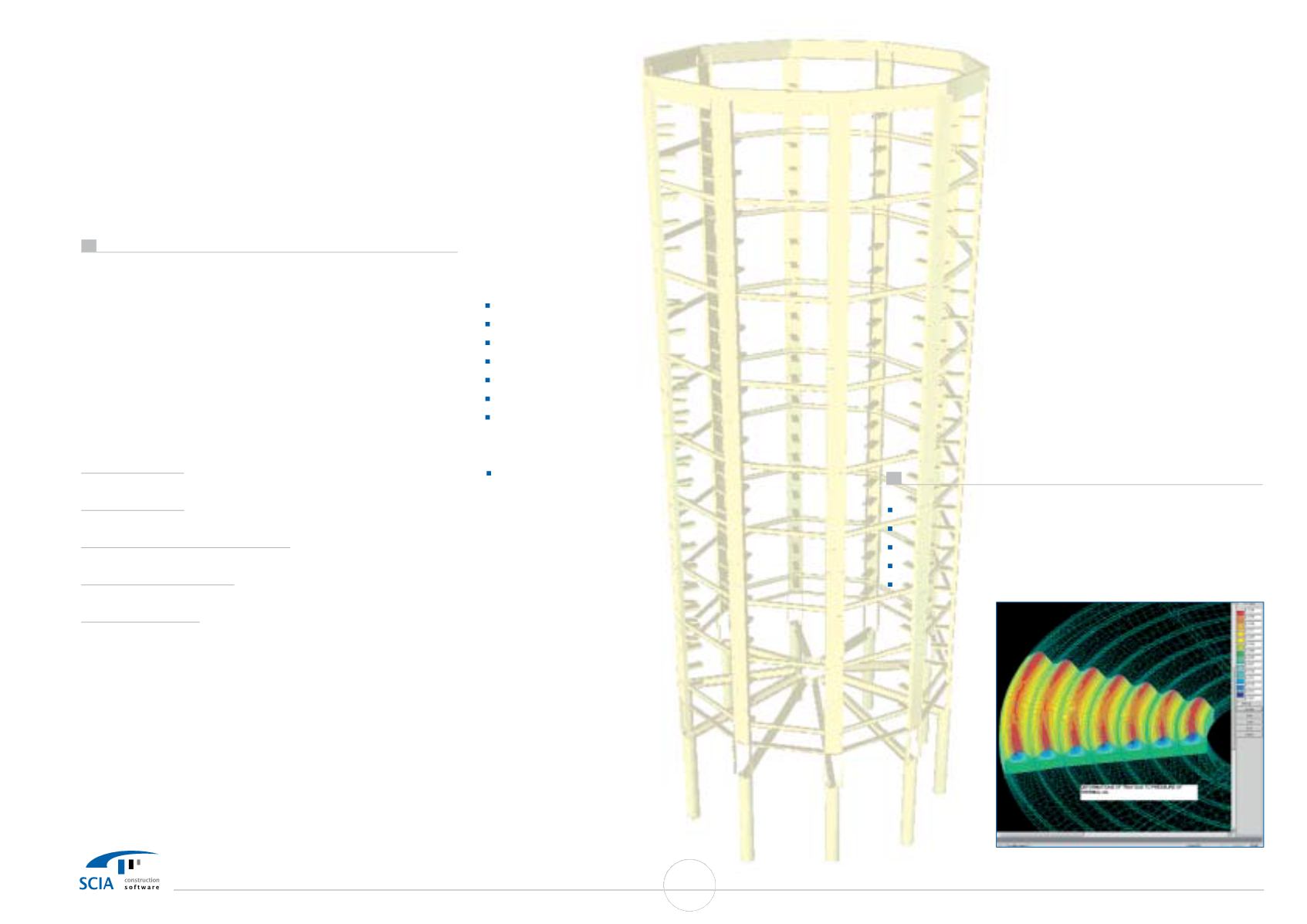
2. Thermal tray as pressure vessel
Since the tray is heated by thermal oil at a pressure of typically
3 bar, the tray actually is a pressure vessel. Therefore, during
design,
model of tray is also loaded with pressure-load case to
calculate resulting stresses and obtain information on
behaviour of stress-concentrations in the tray-structure.
Corrosion calculations
were easily possible by graphically
selecting elements considered as being corroded, reducing
their wall-thickness and recalculate structure.
Tray supports
Because
of the
high importance
of the very limited
deformations of the trays, naturally also a very strict analysis is
done on the tray supports.
Torque Reaction arm of main drive
A reaction arm balances the drive torque of the main drive.
Due to the high mechanical power of the main drive and the
low speed of rotation of the main shaft, this leads to high
reaction forces to be distributed via the reaction arm. This arm
is also designed by using a FEM model:
Use of ESA-Prima Win
Pelletiser Shell structure: 3D shell + 3D frame
EC3-code check
Tray: 3D shell
Supports: 3D shell
Torque Arm: 3D shell
35
SCIA User Contest Catalog


