Your Project:
Typical data:
Reactor dimensions:
Diameter: 9000 mm,
Height cylinder: 10000 mm (incl. skirt)
Height cone:
9800 mm
Steel structure dimensions:
Height: 14400 mm, Base: 7700 mm x 6000 mm
Penthouse dimensions:
Height: 6200 mm, Base: 7800 mm x 4800 mm
Weight:
Ca. 70 tons
Design conditions reactor:
Pressure: -280
-300 mm H2O = 3 kN/m²
Operation temperature:
max. 250 °C
Possible slagging weight of lime:
ca. 40 tons
Overall height of global structure:
ca. 35000 mm
Design of Complete reactor structure
The total reactor-design consists of following parts:
1. Reactor shell structure
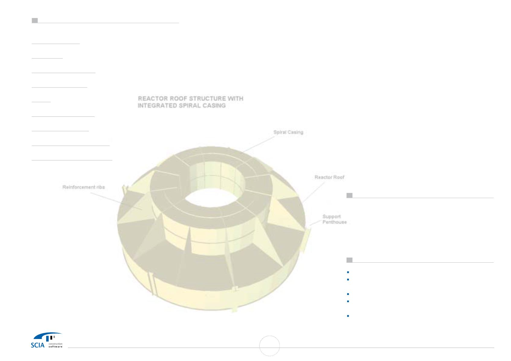
2. Reactor-roof with integrated spiral casing
3. Penthouse and platform on top of Reactor-structure
4. Reactor support skirt design
5. Reactor supporting steel structure
It was necessary to take design decisions in an early stage of
the project; so we decided to start the design on different
items simultaneously and models were made of the different
parts, using approximate boundary conditions and loading
assumptions.
Because the actual structure acts as an
integrated entity, the different parts were assembled one for a
crosscheck calculation using the ESA-Prima Win option to load
(sub) projects into an existing project: it is possible to
"assemble" the different building parts, and simulate the
complete design (wind transfer from penthouse to reactor,
different
support-stiffness
of
reactor-support
due
to
asymmetrical steel structure, combination of
wind load and
pressure in reactor
)
1. Reactor shell structure
For design of this structure use of both global and local axis
systems was made to define loading (wind loading according
to global axes, pressure in reactor according to local axes of
2D elements
) For evaluating results of calculation (stresses in
2D macros), different output calculation facilities were used:
stress SigmaE for interpretation of stress concentrations,
stresses SigmX, Sigm
Y to
make
distinction
between
longitudinal and circumferential stresses in reactor, used to
investigate buckling of reactor (comparison with analytically
calculated buckling stresses). Behaviour of reactor in corroded
conditions
was simulated by graphically selecting elements
(considered as corroded) and reducing
wall thickness and
recalculate structure.
Behaviour of structure at
higher
temperatures
was done reducing E-modulus in calculation
model.
2.Reactor-roof with integrated spiral casing
To analyse the reactor roof and spiral case as a "plate-stiffened
structure" we used the powerful possibility to combine 1D and
2D elements in 1 design: ribs on plates were used to model
stiffeners on plates, using the option of eccentricity to make
the most economical design possible.
To evaluate the reinforcing influence of the spiral case on the
flat reactor-roof, an model of the spiral case was used.
Limitations were put on the deformation of the spiral case
where the Atomiser is mounted. To evaluate the deformations
of the roof +& spiral case in the
workshop (support on 2
beams),
modifications to the existing FEM model
were made.
3. Reactor skirt design
We evaluated the rigidity of the design and the stress
concentration (specifically the stress pattern) near the support
points of the reactor.( using the nodal
mesh refinement option
in these nodes)
4. Penthouse and Support structure
The structures were designed using EC3. The complete model
was used for the cross-check calculation, using actual force
transfers in the reactor and penthouse-supports. The many
possible load cases (wind in x, y direction, pressure in reactor,
lime deposit in reactor cone,
monorail loading of penthouse,
loading of platforms of penthouse and support structure,
insulation weight) this resulted in 596 EC3-combinations!
In 1 of the reactors it was not possible to use bracings; a 2nd
order calculation was done, to get reliable info on sway/non-
sway conditions.
5. Seghers Rotary Atomiser
Lime-milk is sprayed in the reactor using a distributor-plate
turning at ca. 12000 rev/min.
A critical design parameters of
the axle is the "critical speed" (max. speed is limited by
centrifugal forces).
A simplified
method of analysing this
critical speed was done using a 1D-analysis of the axle this
means evaluating deformations in the
magnitude-order of
microns!
It is fascinating how in one global design (Reactor
with
Atomiser) 2 totally different
mechanical structures (Reactor
structure 100 tons,
with cm displacements and Atomiser with
axle 15 kg,
with
micron-displacements) are
met. Since
however both structures behave according to the same laws
of
mechanics and the resulting
mathematical analysis, the
same design software could be used!
Extension of existing stairwell tower
To access the roof & penthouses, the existing stairwell had to
be extended. (18600
mm to 29240
mm) and one of the
stairwell towers was loaded by the 2nd outlet fluegas-channel
of the reactor (weight: 9 tons). To design the necessary
reinforcements to the structure as well as keep reactions to
foundation allowable an "as-built" model
was used.
Use of ESA-Prima Win
3D shell: For separate analysis of different parts of reactor
3D frame: For analysis of support structure and penthouse
structure for simulation calculation of stairwell tower
3D shell + 3D frame: for cross-check calculations
EC3 - check: For calculation of support structure and
penthouse structure
Non-Linearity: extra 2nd order calculation of the support
structures
37
SCIA User Contest Catalog


