wide exchange of personnel between the Tebodin offices.
Services offered by Tebodin EC
Consultancy, site selection
Conceptual studies
Project management
Permitting
Basic and detail engineering
Tendering and procurement
Construction supervision and Commissioning.
These are offered as single engineering or consultancy
packages
or
on
an
EPC-Contract
(Engineering,
Procurement, Construction) or even turnkey basis.
The services and know-how offered by Tebodin EC cover
the following technological areas:
Process Technology
Power Plants
Logistics
Environment
Automotive
Telecommunications
Steel and machine building
Logistics and Manufacturing
Buildings and Infrastructure: Construction, Architecture,
Building physics, Installations, Transport, Estimating/Bid
documents
One of the main activities of Tebodin EC is to provide the
full range of services for new facilities for foreign investors in
Hungary, specifically in the areas of industrial plants,
commercial and logistics centres and infrastructural
development.
Your Project:
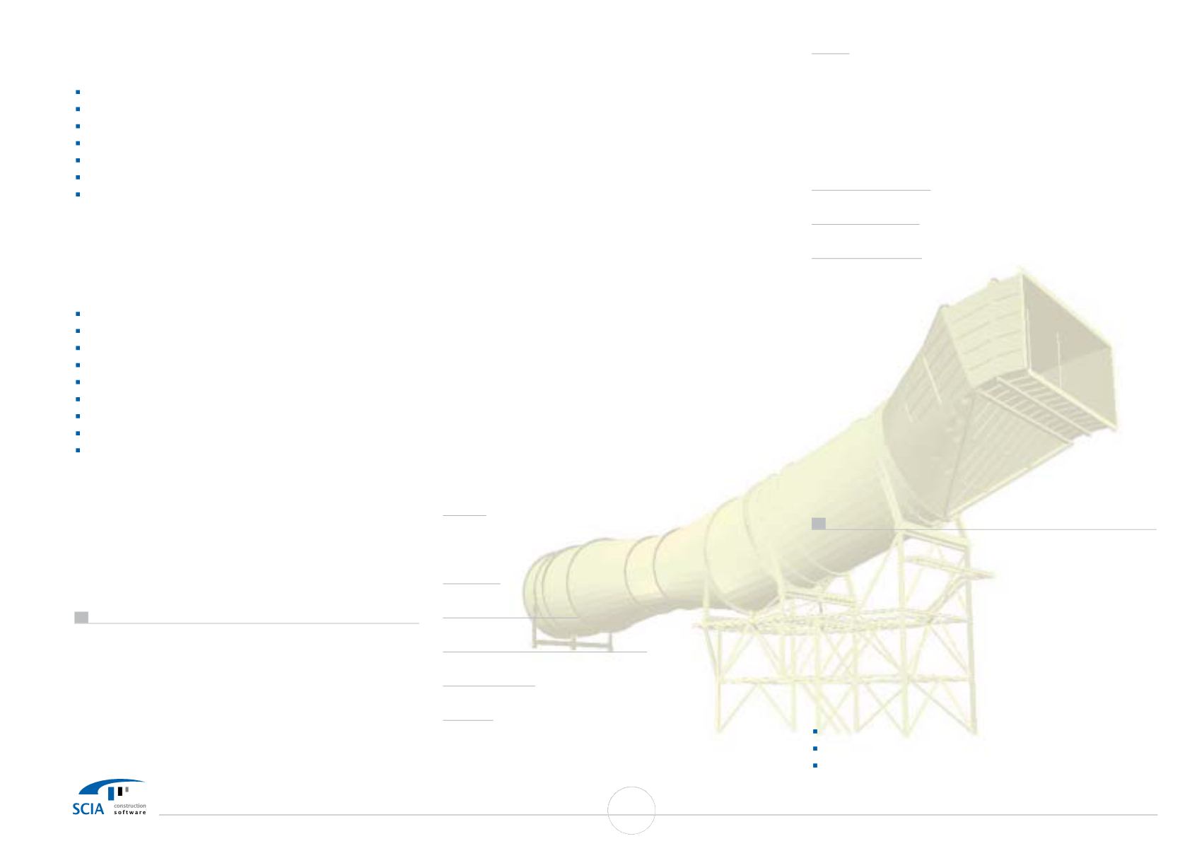
The project covers a power plant in Gyöngyös in Hungary
working with lignit (brown coal). The flue gas contains a
high concentration of SO2 and the plant had to built a new
desulphurization
plant. The two absorbers (so-called
washers) were built in the two cooling towers,
where the
flue gas is transported. The distance between the boiler
houses and the cooling towers is ca. 300-400 m. Tebodin EC
Ltd. had to design the entire system of flue gas ducts
between the electro-filters and the washers in the cooling
towers. Two washers where build and to each ones lead
one flue gas duct (diameter 7400 mm.) In the entire project
the 44 independent part of the duct are separated by
compensators. The compensators are always above the
supporting structures. The model shows a part of the flue
gas ducts, directly before the washer. The system contains
the duct and the supporting structure. There are two types
of ducts in this model. The first type is supported by two
structures (one is a theoretical support & one is the support
given in the model). The other type is supported completely
by the given structure. The first duct is located out of the
cooling tower; and this part is loaded by wind. This duct also
has a part where the cross section is smaller (D=5600 mm)
than the others, because the duct has to pass between the
columns of the cooling tower and the space is very narrow.
The second part of the ducts are connected to the washers
and the cross section is not circle but rectangle (11400x4600
mm). The ducts are insulated by 150 mm thick of
mineral
wool and coated by trapezoid steel plates. The ducts have fix
points and the sliding supports are on the steel structures.
The friction coefficient for sliding supports is 0,10 (applied for
calculated supporting forces of the dead
weight) The
supporting steel structures are "latticed" structures
with
platforms and stairs to access the supports of the ducts.
Technical data of the project
Height:
Centre line of the ducts between the legs of the cooling
tower is on level 11.46 m, Centre line of the instep to the
washer is on level 19.10 m
Diameter:
7400 mm
Thickness of the plates:
8 mm (7 mm design thickness + 1 mm for corrosion)
Total
weight for the whole project:
ducts 2800 to, and the steel structure is 800 to
Designing time:
From February 1998 to August 1999.
Material:
S235JRG2
acc.
DIN-EN
10025 (Yield strength:235
N/mm
2
,
Allowable stress at working temp. (190 C°) is 163
N/mm
2
Loads:
Dead load of the structure by ESA-Prima Win
Dead load of the corrosion's thickness and insulation and
covering: 0.38 kN/m
2
Dead load of grating of the platforms: 0.30 kN/m
2
Live load on platforms: 3.50 kN/m
2
Wind load: basic wind pressure is 1 kN/m
2
(Shape factor
according the rules of the owner)
Pressure in the duct:
+4.00 kN/m
2
/ -2.00 kN/m
2
Temperature load:
190 C° inside, 175 C° outside of the stiffeners
Friction coefficient:
0.10
Combination of loads according to DIN 18800
Stress & stability analysis acc. to
DIN 18800 Part 1 for
supporting steel structure. The buckling of the shells and
plates of the ducts can be examined by hand according to
DIN 18800 Part 3 and 4.
In the model
we can see the maximal stresses in the plates
and shells of the ducts (never bigger than 163/1.1=148
N/mm
2
), the checking of stresses and buckling of the
stiffeners and steel supporting structures, From the model
we can estimate the expectable deformation of the duct in
the connection point with the washer and could suggest
the necessary over lifting of the duct.
Use of ESA-Prima Win
Experiences with ESA-Prima Win
The results given by ESA-Prima Win are the same what we
measured on the site in the reality. The deflections of the
ducts were exactly the same what we had calculated with
the program. It would be useful if the different part of the
model could be got different colors.
And also at rendering
not the whole construction e.g. legs, beams, stairs, plates
has the same color, but we can choose different ones.
Modules used:
Base module
3D shell
Steel Code Check acc.
DIN
41
SCIA User Contest Catalog


