28
X1
Category 1: Buildings
The OV-Terminal and the K5 Office Building are the final
pieces of the complete masterplan of the reconstruction
of the station area in Arnhem, the so-called Phase 2 of
the project. The buildings are located next to each other
and due to the organic forms they smoothly fit into each
other. Both buildings are built on top of the car parking
area, on top of and against the bicycle parking area
(the so-called substructure) and against the K4 and K2
Office Buildings. These structures were already built
in Phase 1 of the project and have a large structural
interaction with each other.
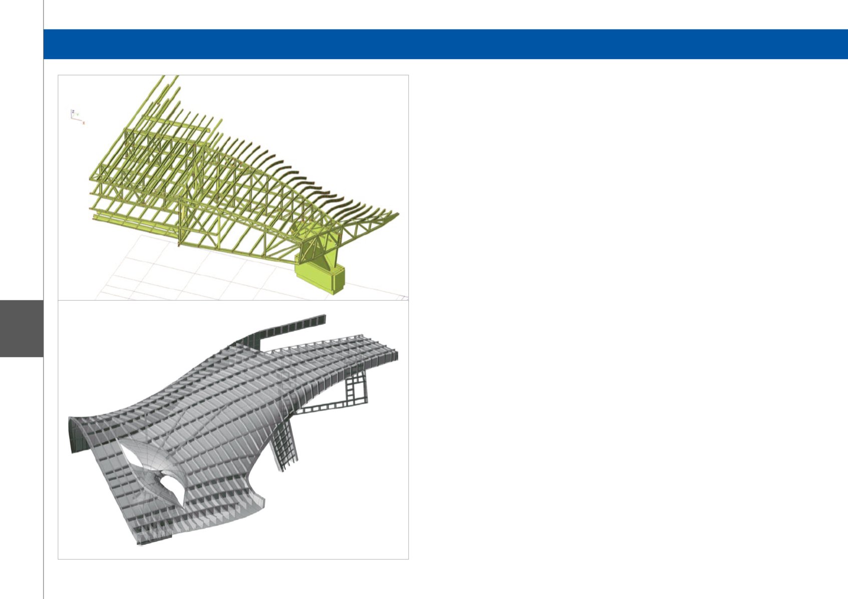
Structure of OV-Terminal
The structure of the OV-Terminal consists of the
structure of the roof and the structure of the balcony and
road bridge. The roof structure is designed in steel and
is basically a ship structure inside out. This structure
is engineered and built by CSC (a ship builder) and
modelled with the FEM-package Ansys. The balcony
and the road bridge are reinforced, in situ concrete
structures with spans of 25 m. The structure of the
balcony is characterised by large beams (1.4 x 1.8 m
2
),
a concrete deck (0.2 m thickness) and a high number
of kinks and inclinations. The road bridge is a concrete
plate structure with weight-reducing elements in
between.
The structure of the balcony and the road bridge is
supported by a limited number of walls, of which some
are inclined. Elements like the flip, the V-walls, the
fronttwist and the backtwist are examples of inclined
supports. This results in large horizontal forces
which transfer through both the structure of Phase 1
(already built) and Phase 2 (current project) to satisfy
equilibrium.
Structure of the K5 Office Building
The K5 Office Building has a steel structure composed
of high truss structures with steel-concrete floor
structures in between. These truss structures are
necessary to support the total building on just six
supports. The truss structures follow the organic form
of the roof and a number of them are twisted, inclined
or both. This also results in horizontal forces which
should make equilibrium within the structure itself. One
support, the so-called ‘trumpet wall’, which supports one
of the trusses, is also inclined and introduces a large
horizontal force of 2.5 MN in the structure of both K5
and the OV-Terminal.
Noteworthy is the fact that the stability of the K5 office
building is provided by the OV-Terminal in one direction
and the K5 wall structure in the other.
Use of Scia Engineer
Scia Engineer is used to model the concrete structure
of the balcony and the road bridge and the steel
structure of K5. The complex forms, kinks and curves
of the structure, the inclinations of the supports and the
complex interaction with the structure of Phase 1 and
the roof made it necessary to model both structures (the
balcony and road bridge of the OV-Terminal, and the
K5 Office Building) in Scia Engineer.
For the balcony and road bridge structure,
Scia Engineer is used to determine the horizontal
and vertical load transfer. For the calculation of the
reinforcement of the beams, integration strips are
successfully applied.
Scia Engineer is used to calculate the load transfer and
to check the steel elements with steel codes.
OV-Terminal and K5 Office Building - Arnhem, The Netherlands
Software: Scia Engineer


