Tunnel Sitiny
Ing. Daniel Bukov OK TEAM
Budatínska 31
851 05 Bratislava
Slovakia
Tel.: +421 63815362
Fax: +421 63537744
Contact:
M.
Daniel Bukov
Email:
For twenty two years I have worked in the
same company, always in connection with
active structural design.
In 1991, after velvet revolution, I started my
own small firm, Ing.
Daniel Bukov OK TEAM,
as one of the many structural engineers in
Slovakia.
From the year 2001 on, I
worked as a pri-
vate structural designer mostly for concep-
tual structural design and calculation.
During this time lot of things changed in
professional life: efficiency of computers,
operating systems and of course computers
programs. In the beginning, I
worked with
computer
programs
NE-XX, SAPIV run
under DOS later on with STRAP, STAAD and
of course with ESA-Prima Win.
Many of
my structural analysis
were per-
formed for mechanical parts as pipes with
large diameter, some technological projects
including tanks silos and pressure vessels.
In general
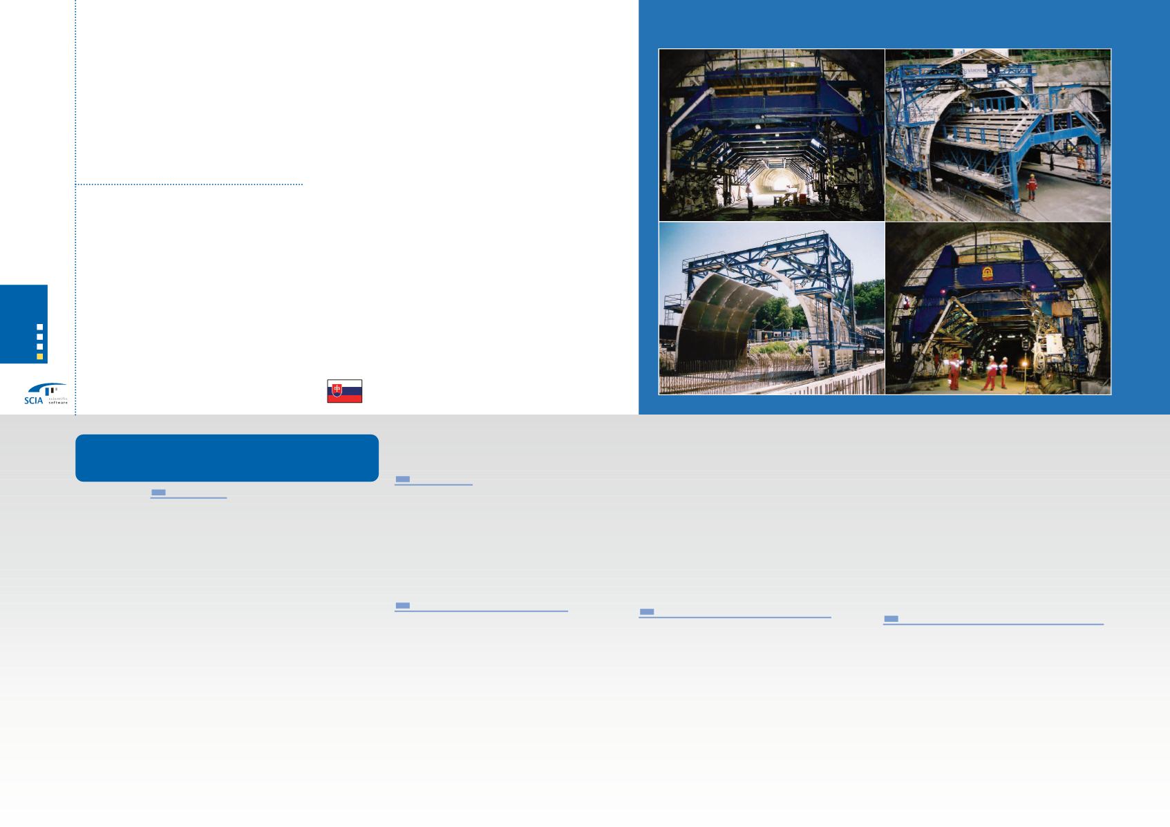
The SITINY tunnel is erected in Bratislava as
a part of the D2 highway which connects
Bratislava with Brno. The project concerns
two parallel tunnels, each with a width of
approximately 8200 mm, a height of 8000
mm and a length of 1160 m. The main con-
tractors for the tunnel are TAISEI, a Japan-
ese Company, Skanska from Sweden and
Banske stavby of Slovakia.
The formwork of the tunnels has been fabri-
cated and erected by the company PORTA
s.r.o., Slovakia. The structural calculation
was performed by Ing.Daniel Bukov
OK
TEAM Slovakia. The subject of the structural
calculation
was the calculation of various
types of tunnel shuttering.
One of them is
presented in detail and the rest is presented
by photos. The main task of the structural
calculation was the check on the mechani-
cal resistance of the tunnel formwork. The
calculation
was based on shop drawings
and requirements of the customer.
Input date
Assembly drawings of the formwork.
Requirements on the speed of pouring con-
crete and input on different levels.
The speed limit for pouring of concrete is
max 1,5 m /hour. The maximum level of the
concrete between two sides is 1,0 m.
Description of the structure
The steel structure of the formwork is creat-
ed from segments of 1980
mm
width,
which are reinforced by ribs. Ribs are creat-
ed from bended steel plates,
which are
welded to the shell of formwork. Segments
are connected in the cross section of the
tunnel by pins. In longitudinal direction,
segments are connected by special bolted
connections.
Connected segments are rein-
forced inside the formwork by a system of
beams and struts. For transporting the form-
work in longitudinal direction, a transporta-
tion carriage was designed. Transportation
carriages consist from two parallel truss
beams and two end cross frames.
Cross frames are designed from box beams
and longitudinal truss beams are designed
from roll shape beams.
All parts of the transportation carriage,
excluded end frames, are parts of a cross
reinforced tunnel formwork. The calculation
of the outside shuttering was performed by
the NEXIS/ ESA-Prima Win program.
Assumptions of the calculation
The loads of the formwork are considered
according to STN 73 0035 with the parame-
ters mentioned below:
The speed of pouring concrete is max 1,5
m/hour (measured in the cross section of
the tunnel)
The maximal different concrete level of the
opposite site is 1 m.
The temperature of the fresh concrete is not
less than 10° C
The settlement of the fresh concrete cone is
done according to STN 73 1312 max 60 mm
The vibration compaction is 100 %
The first layer of the concrete up to 800 m
will be poured uniformly on both sides of
the tunnel.
On top of the cross beam in the space of the
passage area of the formwork, the load may
not exceed 1,5 kPa or 5kN/m of the beam
Checks of the steel
members are done
according STN 73 14 01
Method of the structural calculation
The structural calculation of the formwork
has
been
done
by the Finite Element
Method (FEM). For the calculation of inter-
nal forces, 3D beams and a shell
model
were created. Separate load cases were cre-
ated for each hour of pouring. The different
level of the concrete
was also considered.
Supports were considered as stiff for the ver-
tical direction and flexible for the horizontal
direction.
With regard to the flexibility of
supports, effects of the friction between
158
Company
Project
Tunnel Sitiny - Tunnel Formwork
structural calculation
Ing. Daniel Bukov
OK TEAM
SCIA User Contest 2005 / Steel constructions
4
Categorie


