supports and concrete base were simulated. The
stiffness of the supports was designed by the rule
that the results of horizontal force had to be less
than 10 % of the vertical force. From separated
load cases, design combinations were created.
All
members are checked according to STN 73
1401 for ULS. In shell elements stresses are also
checked.
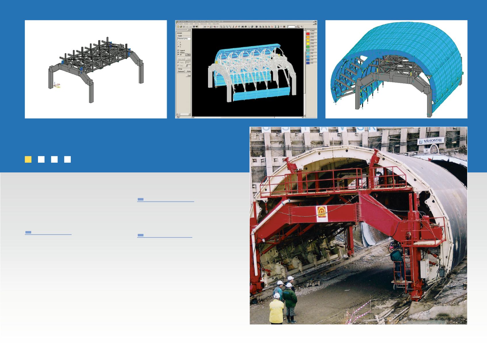
Structural
model
The structural
model of the tunnel shuttering, as
mentioned above,
was created by the FEM
method. For modelling the shell of the shuttering
(a part of which is directly contact with the con-
crete), the reinforced ribs of the shell, the struts,
fixed shell elements were used.
With regard to
the poured concrete, hydrostatic pressure free
loads were used. Each segments of the shutter-
ing is a model (two webs on each part, very close
to each other). Between the two ribs, short
beams with a node in the middle were created.
Working
with such a huge
model
without the
use of macro elements and without the possibili-
ty to
make some parts invisible is practically
impossible.
ESA-Prima Win/NEXIS
made the computational
model creation possible.
Codes and standards
Loads are calculated according to STN 73 0035
(86)
Members are checked according to STN 73 1401
(98)
Computer programs
Internal forces (forces and stresses) calculation is
perform by FEM
with
NEXIS-ESA-Prima
Win
32.50.10
For rest of calculations,
MC 2001 (by MathSoft
USA) was used.
159


